Potential Dividers (Cambridge International IGCSE Physics)
Variable potential dividers
Spec point —
4.3.5· Describe the action of a variable potential divider
Extended Tier Only
- When two resistors are connected in series, the potential difference across the power source is shared between them
- A potential divider is a circuit which splits potential difference from a power source, so only a fraction goes to a component (a voltmeter, in the diagram below)
Potential divider diagram
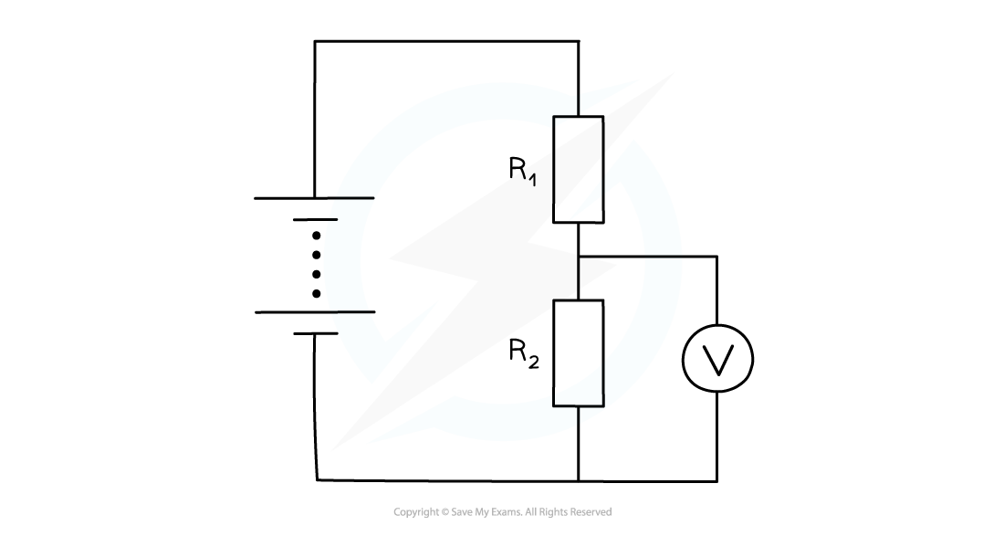
A potential divider splits the potential difference of a power source between two components
-
The potential difference across each resistor depends upon its resistance:
- The resistor with the largest resistance will have a greater potential difference than the other one
- If the resistance of one of the resistors is increased, it will get a greater share of the potential difference, whilst the other resistor will get a smaller share
-
If one resistor is a variable resistor, the potential difference across the other resistor can be altered
- This means the potential difference across any component in parallel with that resistor can also be altered
Resistors as potential dividers
Spec point —
4.3.5· Recall and use the equation for two resistors used as a potential divider R1/R2 = V1/V2
Extended Tier Only
-
When two resistors are connected in series, the power source's e.m.f. is split between the resistors
- This potential difference splits in the same ratio as the resistance of the two resistors
-
The ratio of potential differences across each resistor can be found using the following equation:
-
Where:
- is the resistance of resistor 1 in ohms, Ω
- is the resistance of resistor 2 in ohms, Ω
- is the potential difference across resistor 1 in volts, V
- is the potential difference across resistor 2 in volts, V
-
Recall that the e.m.f. of the power source will be equal to
Worked Example The circuit is designed to light up a lamp when the input voltage exceeds a certain value.
When the lamp lights up, is 5.3 V.
Calculate the e.m.f. of the power source required to illuminate the lamp.
[3]
Answer:
Step 1: List the known quantities
- Resistance of resistor 1,
- Resistance of resistor 2,
- Potential difference across resistor 2,
Step 2: Recall the equation for a potential divider
Step 3: Substitute the known quantities and determine the potential difference across resistor 1
[1 mark]
Step 4: Determine the e.m.f. of the power source,
[1 mark]
- The e.m.f. of the power source when the lamp illuminates is 8.5 V to 2 significant figures [1 mark]

Exam Hint When thinking about potential dividers, remember that the higher the resistance, the more energy it will take to 'push the current through', and therefore the higher the potential difference.
This means that if a component (often shown as a voltmeter in questions) needs to be switched on by a change such as increased light or temperature, then the resistor it is in parallel with needs to become larger compared to the other resistor.
Was this revision note helpful?
Build on this topic