Rectification (Cambridge International A-Level Physics)
Rectification Graphs
-
Rectification is defined as: The process of converting alternating current and voltage into direct current and voltage
-
Rectification is used in electronic equipment which requires a direct current
- For example, mains voltage must be rectified from the alternating voltage produced at power stations
Types of rectification
-
There are two types of rectification:
- Half-wave rectification
- Full-wave rectification
-
For half-wave rectification:
- The graph of the output voltage Vout* against time is a sine curve with the positive cycles and a flat line (Vout *= 0) on the negative cycle
- This is because the diode only conducts in the positive direction
-
For full-wave rectification:
- The graph of the output voltage Vout* *against time is a sine curve where the positive cycles and the negative cycles are both curved ‘bumps’
Half and full wave rectification
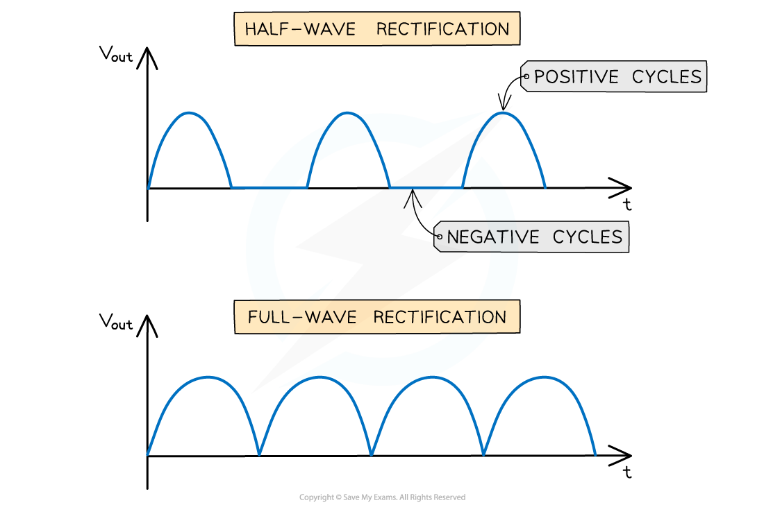
The difference between the graphs of full-wave and half-wave rectification
Half-Wave Rectification
Spec point —
21.2.2
-
Half-wave rectification consists of a single diode
- An alternating input voltage is connected to a circuit with a load resistor and diode in series
-
The diode will only conduct during the positive cycles of the input alternating voltage
- Hence there is only current in the load resistor during these positive cycles
-
The output voltage Vout* *across the resistor will fluctuate against time in the same way as the input alternating voltage except there are no negative cycles
Circuit diagram for half-wave rectification
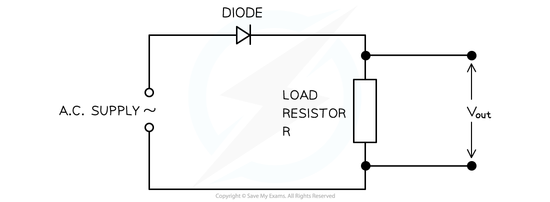
Half-wave rectification requires a single diode and the graph is represented by only the positive cycles
-
This type of rectification means half of the time the voltage is zero
- So, the power available from a half-wave rectified supply is reduced
Full-Wave Rectification
-
Full-wave rectification requires a bridge rectifier circuit
- This consists of four diodes connected across an input alternating voltage supply
-
The output voltage Vout* *is taken across a load resistor
-
During the positive cycles of the input voltage, one terminal if the voltage supply is positive and the other negative
- Two diodes opposite each other that are in forward bias will conduct
- The other two in reverse bias will not conduct
- A current will flow in the load resistor with the positive terminal at the top of the resistor
-
During the negative cycles of the input voltage, the positive and negative terminals of the input alternating voltage supply will swap
- The two diodes that were forward bias will now be in reverse bias and not conduct
- The other two in reverse bias will now be in forward bias and will conduct
- The current in the load resistor will still flow in the same direction as before
Circuit diagram for full-wave rectification
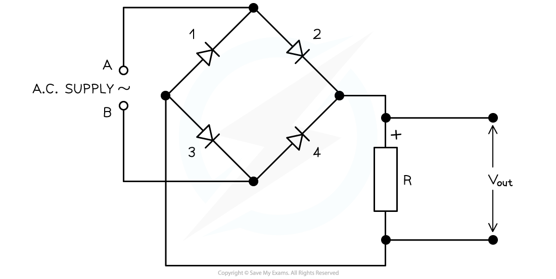
When A is positive and B is negative, diodes 2 and 3 will conduct and 1 and 4 will not. When A is negative and B is positive, diodes 1 and 4 will conduct and diodes 2 and 3 will not. The current in the load resistor R will flow downwards
-
In both the positive and negative cycles, the current in the load resistor is the same
-
Each diode pair is the same as in half-wave rectification
- Since there are two pairs, this equates to full-wave rectification overall
-
The main advantage of full-wave rectification compared to half-wave rectification is that there is more power available
- Therefore, a greater power is supplied on every half cycle
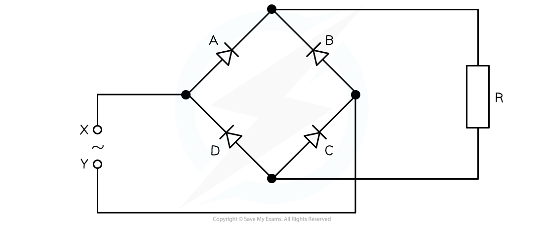
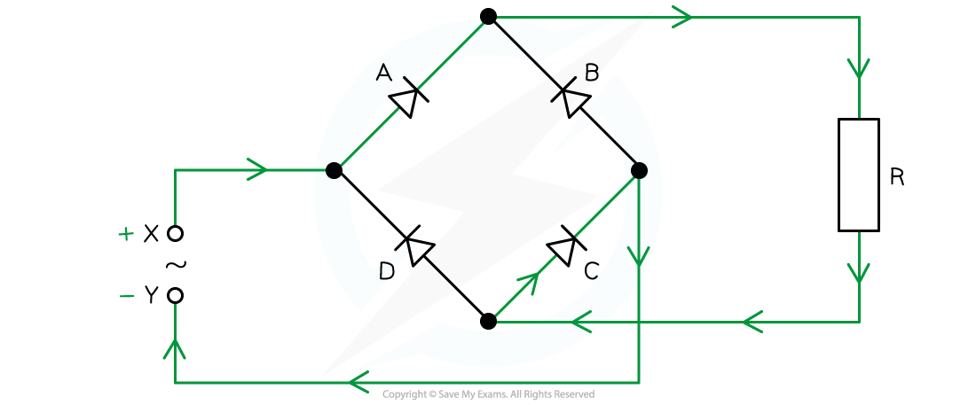
Worked Example A bridge rectifier consists of four ideal diodes A, B, C and D as connected in the figure shown below:
An alternating supply is applied between the terminal X and Y.
State which diodes are conducting when terminal X of the supply is positive.
Answer:
- Draw the path of the current direction with diodes in forward bias
- Remember that conventional current flow is from positive to negative and only travels through the paths with diodes in forward bias
- Therefore, the answer is: diodes A and C
Was this revision note helpful?