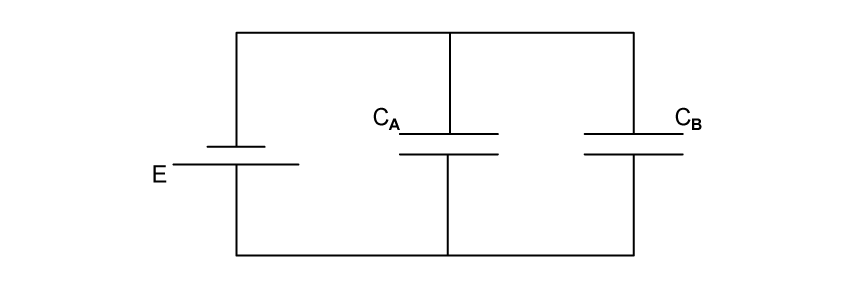
Two capacitors, X and Y, of capacitance 25 μF and 88.5 μF respectively, are connected in parallel to a battery of emf 6.0 V, as shown in Fig. 1.1
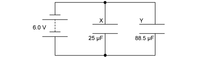
Fig. 1.1
The plates of both capacitor X and capacitor Y are separated by a vacuum.
Complete Table 1.1 for this circuit.
Table 1.1
| capacitor | capacitance / μF | p.d. / V | charge / μC |
|---|---|---|---|
| X | 25.0 | ||
| Y | 88.5 |
Extract:
Two capacitors, X and Y, of capacitance 25 μF and 88.5 μF respectively, are connected in parallel to a battery of emf 6.0 V, as shown in Fig. 1.1. Fig. 1.1. The plates of both capacitor X and capacitor Y are separated by a vacuum. Capacitor X: capacitance 25.0 μF; Capacitor Y: capacitance 88.5 μF.
The total capacitance for two capacitors and connected in parallel is given by the equation:
Using the equation given, calculate the total capacitance of the circuit shown in Fig. 1.1 in Farads, F.
Extract:
Two capacitors, X and Y, of capacitance 25 μF and 88.5 μF respectively, are connected in parallel to a battery of emf 6.0 V, as shown in Fig. 1.1. The plates of both capacitor X and capacitor Y are separated by a vacuum.
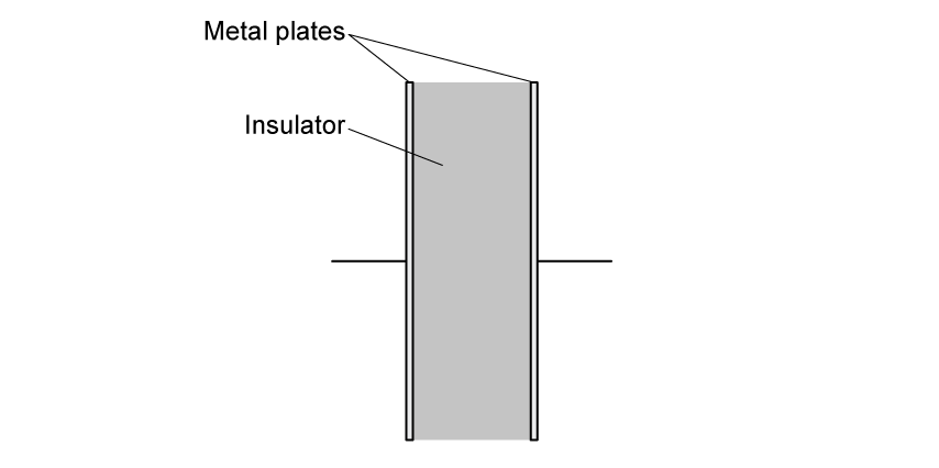
A dielectric material is inserted into the space between the plates of capacitor Y in Fig. 1.1.
State how the capacitance of capacitor Y changes with an added dielectric material.
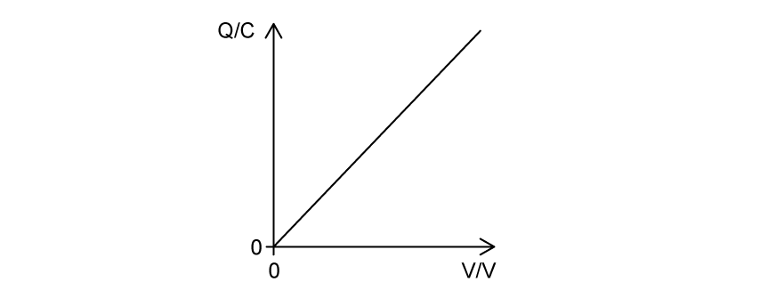
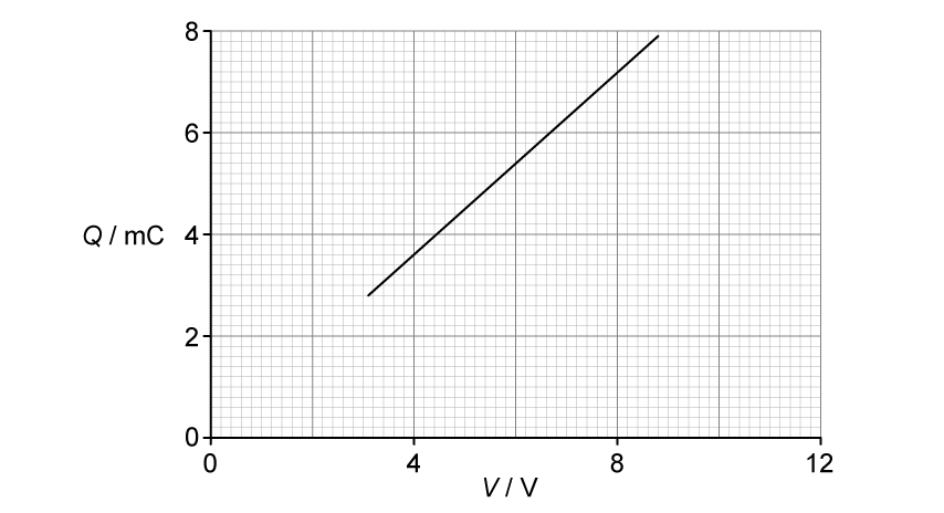
The graph in Fig. 1.2 represents the equation Q = CV.

Fig. 1.2
State the quantities represented by each axis.