Adders & Circuits (Cambridge International A-Level Computer Science)
Half adders
What is a half adder circuit?
- A half adder circuit is a basic digital circuit used in computation to perform the **addition **of two single bit numbers
- Has** two inputs**, usually labelled as **A **and B
- Produces** two outputs** labelled Carry out (Cout) and Sum(s)
| A | B | Cout | S |
|---|---|---|---|
| 0 | 0 | 0 | 0 |
| 0 | 1 | 0 | 1 |
| 1 | 0 | 0 | 1 |
| 1 | 1 | 1 | 0 |
| A AND B | A XOR B |
-
Remember that you are adding together the binary numbers represented by A and B
-
Create the Coutcolumn first then for each row you can just add A and B together and write the answer in 2 bits in the Cout and S columns
-
For example in row 2:
- A is 0 and B is 1 and 0+1=1
- 1 = 01 in 2 bits (Cout 0 and Sum 1)
-
In the last row:
- A is 1 and B is 1 and 1+1 = 2
- 2 = 10 in 2 bit binary (Cout 1 and Sum 0)
-
Drawing a half adder circuit
-
A half adder circuit has two inputs, typically labelled as A and B, and two outputs: the Sum(S) and **Carry **(Cout)
-
This circuit can be created using an** XOR gate for the Sum output** and an AND gate for the Carry output
-
Label Inputs:
- Begin by drawing two lines on the left side of your paper or drawing space
- Label the top line as 'A' and the bottom line as 'B'
- These represent your inputs
-
XOR Gate (Sum):
- Draw an XOR gate (often a shape like a curved 'D' or a shape similar to an OR gate but with an additional curved line on the input side) in the middle of the paper or drawing space
- Connect the A and B lines to the two inputs of the XOR gate
- The output from the XOR gate is the 'Sum'
- Draw a line from the output of the XOR gate to the right side of your paper and label it as 'S'
-
AND Gate (Carry):
- Draw an AND gate (typically a D-shaped symbol) above the XOR gate
- Again, connect the A and B lines to the two inputs of the AND gate
- The output from the AND gate is the 'Carry'
- Draw a line from the output of the AND gate to the right side of your paper and label it as 'Cout'

Half Adder Logic Gates
Full adders
What is a full adder circuit?
- A full adder circuit extends the half adder to handle the addition of three bits
- Has three inputs: A, B, and an input carry (Cin)
- Produces two outputs: carry (Cout) and sum (S)
| A | B | Cin | Cout | S |
|---|---|---|---|---|
| 0 | 0 | 0 | 0 | 0 |
| 0 | 0 | 1 | 0 | 1 |
| 0 | 1 | 0 | 0 | 1 |
| 0 | 1 | 1 | 1 | 0 |
| 1 | 0 | 0 | 0 | 1 |
| 1 | 0 | 1 | 1 | 0 |
| 1 | 1 | 0 | 1 | 0 |
| 1 | 1 | 1 | 1 | 1 |
-
To easily reproduce this Truth Table, remember:
- The full adder adds up three binary inputs A,B and C
- So the answer can be 0,1,2 or 3
- For each row, add up A, B and C and the write the answer as a 2 bit binary number in the last 2 columns (Cout and Sum)
- For example in row 4, A=0, B=1 and C=1 -0+1+1=2 which is 10 in binary, so Coutis 1 and Sum is 0
- In the last row, A=1, B=1 and C=1, 1+1+1=3 which is 11 in binary so Coutis 1 and Sum is 1
Operation
- The "Sum" output provides the XOR of the inputs A, B, and Cin
- The "Carry" output is TRUE if at least two of the inputs A, B, and Cin are TRUE
Drawing a full adder circuit
-
A full adder circuit consists of three inputs: A, B, and Carry (Cin), and two outputs: Sum (S) and Carry (Cout)
-
It can be designed using two half adders and an OR gate
-
Label Inputs:
- Start by drawing three lines on the left side of your paper or drawing space
- Label the top line as 'A', the middle line as 'B', and the bottom line as 'Cin'
- These represent your inputs
-
First Half Adder:
- Draw a half adder with A and B as inputs
- This consists of an XOR gate (for the Sum) and an AND gate (for the Carry)
- Label the output of the XOR gate as 'Sum1' and the output of the AND gate as 'Carry1'
-
Second Half Adder:
- Draw a second half adder underneath the first, using Sum1 and Cin as inputs
- Again, it consists of an XOR gate (for the Sum) and an AND gate (for the Carry)
- Label the output of the XOR gate as 'S' (final Sum) and the output of the AND gate as 'Carry2'
-
OR Gate:
- Draw an OR gate to the right of the half adders
- Connect Carry1 and Carry2 to the inputs of the OR gate
- The output of the OR gate is the final Carry (Cout)
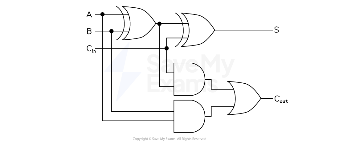
Full Adder Logic Gates
Was this revision note helpful?