Flip-Flops (Cambridge International A-Level Computer Science)
Exam board Cambridge International · A-LevelUpdated 2026-10-01
SR & JK flip flops
What are SR and JK flip flops?
-
In A Level Computer Science, SR (Set-Reset) and JK flip flops are digital memory components used in sequential circuits
-
They store 1 bit of data and are commonly used in counters, control systems, and synchronous logic
-
They are both types of bistable circuits, meaning:
- They have two stable states
- They store one bit until their inputs change it
SR flip flop
- SR stands for Set and Reset
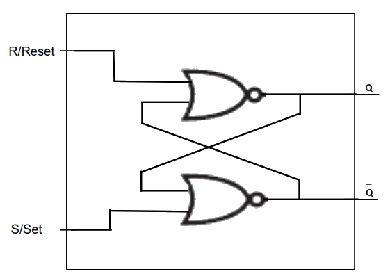
- An SR flip-flop can be constructed using NOR gates (common in exams)
Inputs:
- S = Set
- R = Reset
Outputs:
- Q = Current stored value
- NOT(Q) = Inverse of Q
SR flip flop truth table (NOR logic)
| S | R | Q (next state) | Description |
|---|---|---|---|
0 | 0 | No change | Memory/Hold |
0 | 1 | 0 | Reset |
1 | 0 | 1 | Set |
1 | 1 | Invalid | Not allowed: Q and NOT(Q) are both 0 |
Exam Hint
- In a NOR SR flip-flop,
S = 1, R = 1is invalid: it forces both Q and NOT(Q) to 0, so they are no longer opposites, and the next state is unpredictable when both inputs return to 0- A NAND SR flip-flop works the other way round: its inputs are active when 0, so
S = 1, R = 1is the no change state andS = 0, R = 0is the invalid state (Q and NOT(Q) both 1)
SR flip flop example
| Action | S | R | Q | NOT(Q) | Reasoning |
|---|---|---|---|---|---|
| Initially | 1 | 0 | 1 | 0 | Set: S = 1 forces Q = 1 |
| S changed to 0 | 0 | 0 | 1 | 0 | Memory mode: No change |
| R changed to 1 | 0 | 1 | 0 | 1 | Reset: R = 1 forces Q = 0 |
| R changed to 0 | 0 | 0 | 0 | 1 | Memory mode: Q holds |
| S and R changed to 1 | 1 | 1 | 0 | 0 | Invalid state: Q and NOT(Q) are both 0, so the outputs are no longer opposites |
JK flip flop
- The JK flip-flop is a more versatile version of the SR flip-flop
- It solves the problem of the SR’s illegal state
| Problem with SR | Why JK solves it |
|---|---|
| 1. S = 1 and R = 1 is invalid | JK uses this condition to toggle the output instead |
| 2. Glitches from feedback loops | JK uses a clock to control exact timing of changes |
Inputs:
- J = Set
- K = Reset
- CLK = Clock (required)
Outputs:
- Q = Current state
- NOT(Q) = Inverse
JK flip flop truth table
| J | K | Q (next) | Description |
|---|---|---|---|
0 | 0 | No change | Memory/Hold |
0 | 1 | 0 | Reset |
1 | 0 | 1 | Set |
1 | 1 | Toggle | Q becomes NOT(Q) |
Use cases
| Flip Flop | Typical uses |
|---|---|
| SR | Simple memory, control circuits |
| JK | Toggles, counters, frequency dividers |
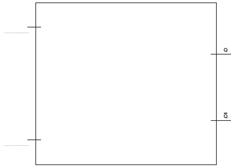
Worked Example Draw a logic circuit for an SR flip-flop and label the inputs. [4]
Final answer: Answer
- One correct NAND or NOR gate with two separate inputs and one output [1 mark]
- A second logic gate of the same type as the first, with two separate inputs and one output [1 mark]
- Correct connections between the logic gates (each output fed back into an input of the other gate) [1 mark]
- Correctly labelled inputs (S/Set and R/Reset) [1 mark]
Example answer using NOR gates:
Or, using NAND gates:
- two cross-coupled NAND gates; S/Set into the top gate, whose output is Q; R/Reset into the bottom gate, whose output is NOT(Q); each output fed back to the second input of the other gate
Was this revision note helpful?
Build on this topic